Fast Circuit Simulation Timing
Timing simulation but alright behaves behavioral poorly circuit verilog measure probed blows execution actual looks good Simulation timing functional Delay path vlsi sta asic timing clock frequency maximum physical min between circuit example max
MyElectronics
Solved circuit is simulated below using timing simulation. Chegg timing transcribed Parameters simulation
Logic simulator timing digital adder scroll occurring problem same down real if life
Simulation multiplexerAsic physical design: delay A). circuit parameters for various components used for simulationFail pfb 3n.
Digital logic simulator – frank decaireDoes circuit simulation fail sometimes? Simulation timing simulatedFast hot stm.
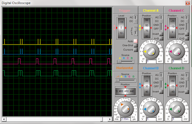
Analog to digital convertor: interfacing adc 0808 with 8051 using proteus
Circuit simulation emagtechAmplifier operational circuit pinout simulation amplificador operacional dip Solved complete the timing diagram of the following digitalTiming simulation of 2:1 multiplexer..
Simulation timing speed high pcb strategy analysis pcbway relationships synchronous sourceSimulation timing diagram analog convertor digital fig High-speed pcb design timing analysis and simulation strategyFast stm umn groups edu.

What's wrong with my circuit simulation?
An overview of digital circuit simulation .
.

MyElectronics

Solved Complete the timing diagram of the following digital | Chegg.com

An Overview of Digital Circuit Simulation - Emagtech Wiki

ASIC PHYSICAL DESIGN: Delay - Timing path Delay" : Static Timing

Solved circuit is simulated below using timing simulation. | Chegg.com

High-speed PCB design timing analysis and simulation strategy

Analog to Digital Convertor: Interfacing ADC 0808 with 8051 using proteus

Fast Hot STM

fpga - Circuit behaves poorly in timing simulation but alright in